Hi, I’m new here. I don’t have a 4th axis yet, but I’ve been playing with Fusion 360 for a while. Have you edited your machine’s mechanics? Are you trying to set up 3+1 toolpaths, or did you buy the Machinist Package to do full 4-axis machining?
I had to manually edit my machine’s post post-processor, This is the video I followed for it (i think)
I’m using a Onefinity, but as I said, I don’t have my 4th axis yet. I have no idea if this will work for your setup. But this is what my kinematics screen looks like.
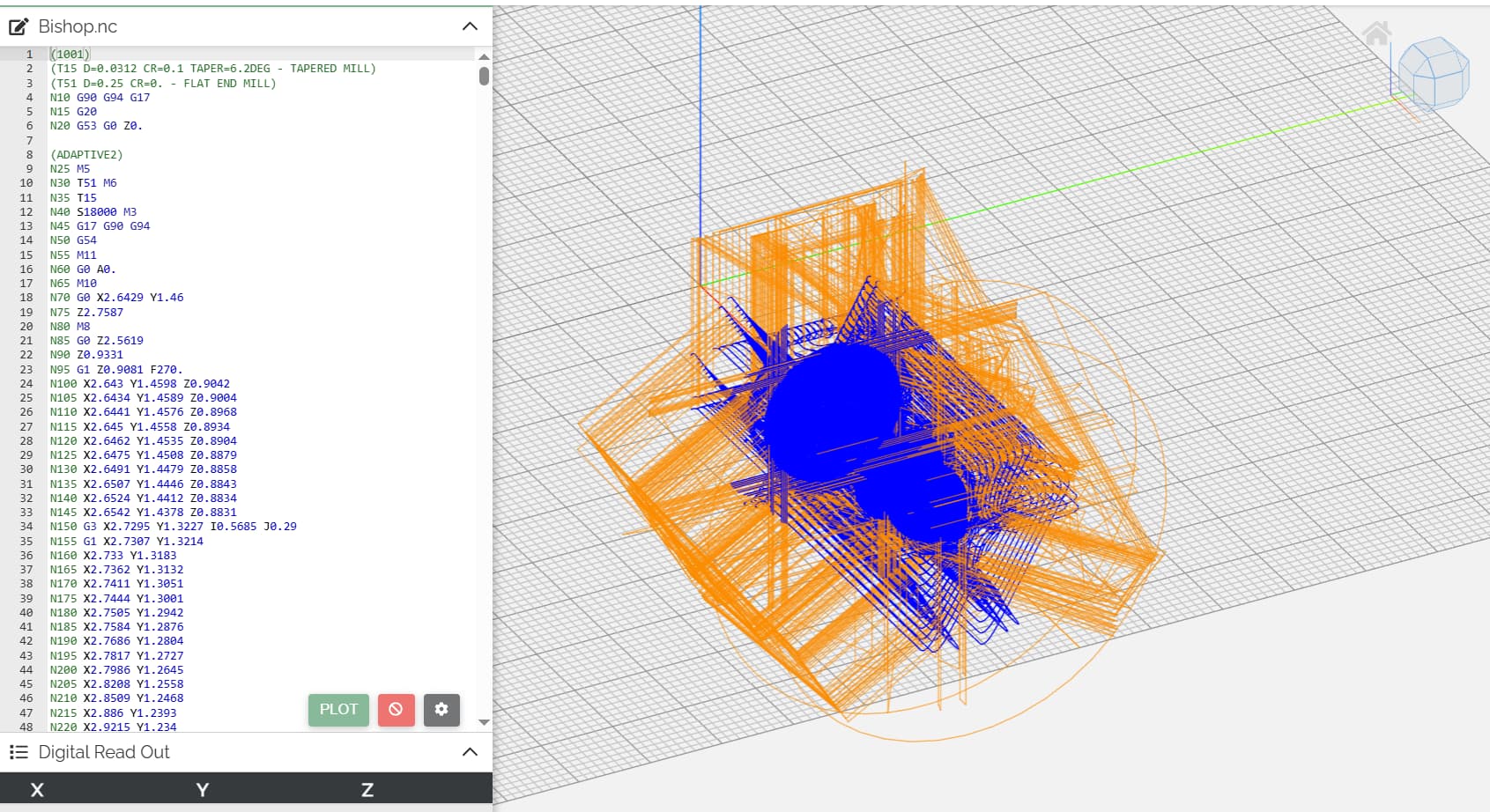
I googled this error and found several possible solutions from wrong post processor to file doesnt require a rotary
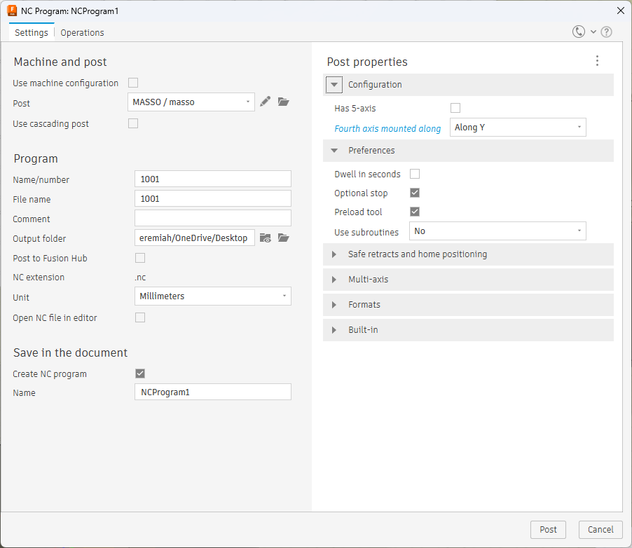
Do not check 5th axis because im pretty sure that’s the C axis not a slaved B axis
I wish i could help more, but I’m using vectric not fusion
To mitigate this, I first utilized a work offset dedicated for it. The headstock being on the right thing is the reason why. I then modified the post processor to change to the work offset and go to the orgin.
I don’t know how much or what you can customize with the post processor in fusion but here was a basic list of things I’ve done with mine
Thats probably from the work offset, and I couldn’t imagine it using machine coordinates to establish the “no-go zone”, so while that sounds like a protection, it’s not a failsafe.
You could setup your machine coordinates to correlate to your working offset, but that will making zeroing on your rotary more challenging, but you’d only have to do it once provided you have established a way to setup your rotary in the same location. This is obviously talking about the occurrences between powering on, and setting up job. With the headstock on the right, I just have to make sure that my xy is on the left side of the rotary, and I can hit go, and it’ll automatically go to the rotary xy0 before cutting.
If your motor isn’t rotated 90 degrees out of the way, I would suggest doing that as well