
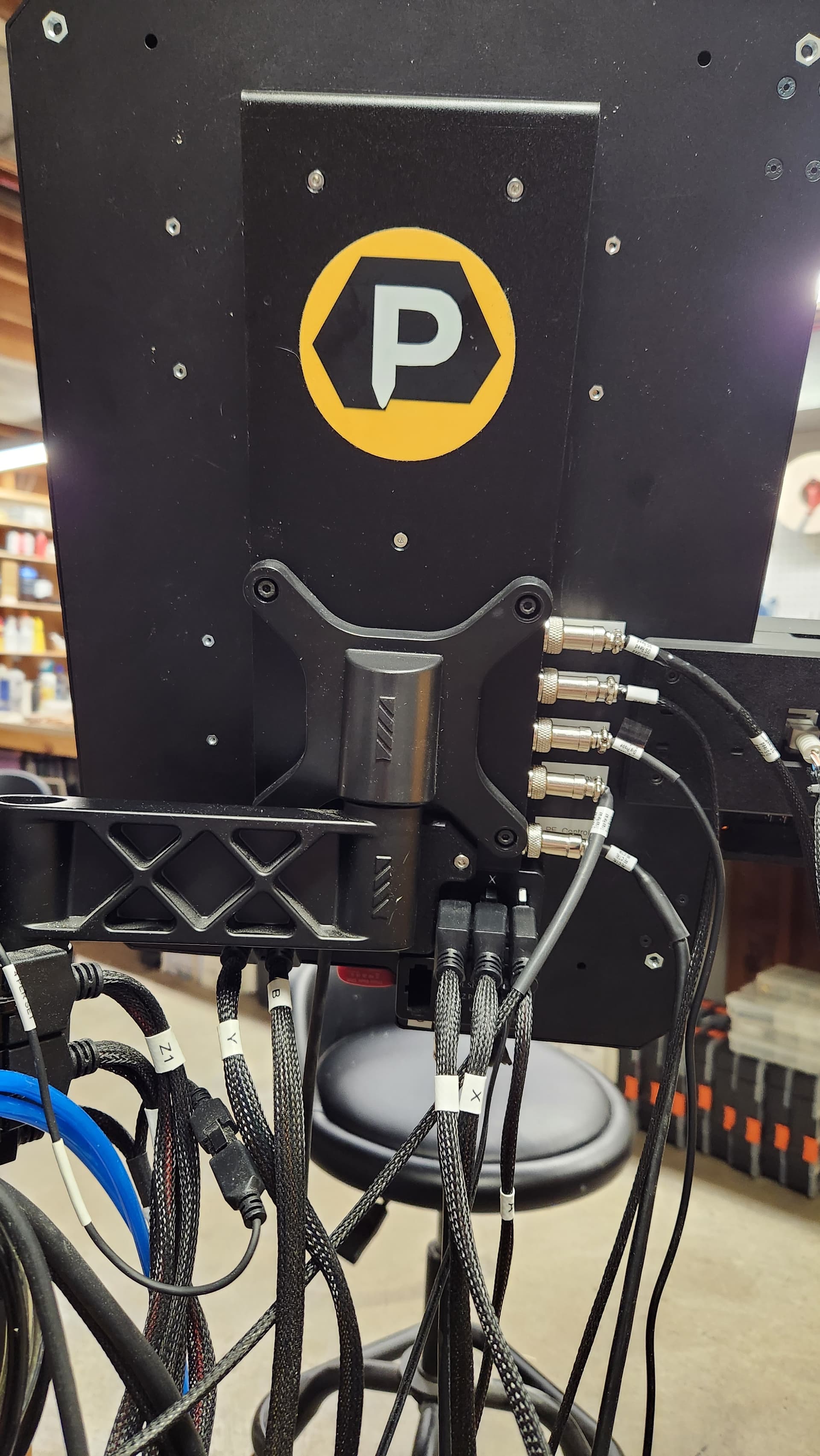
I installed this this morning and the only glitch i encountered was the bracket screws, the one on the original Masso were M5’s and the new riser’s were M4’s
So I scrounged up the right screws from my parts bin.
I have not added the bottom cover plate yet as I am wating on connectors from Amazon to complete 4 more connections…
All in all pretty straightforward…
I used a flag labeler to mark all the wires to their location in the input and outputs. Didn’t trust my aging eyesight and short term memory.
I saw where you said you were providing those M4’s for the mount, so i guess my pakage was just shorted those…
Thanks for the feedback. I’ll pass along the mounting screws weren’t included. Might need to repack our screw bag
I added labels to mine. It wasn’t how i envisioned it looking for my setup. I have to move a connector down due to wire length, but i didn’t have to label the wires since it’s obvious (to me) what the wires go to.

1 Like
My wiring inside the G3 is a rats nest. So I’m going to reroute and label everything inside, then after everything is connected and working I’ll label up the outside. You’re looking good. Have you rewired the X Y Z B connections, they weren’t showing in your pic?
No, those are the only ones left. They weren’t plugged in, and i still haven’t powered my machine since the upgrade
I pulled the Molex chip for the laser / tool setter / probe. Replacing the rest of the molexes is on the docket, but not today. Then down the line farther maybe some cable sleeve inside. Still got my eyes on a couple other accessories before then though.
When removing the stock XYZAB ports, that whole piece holding it is going also, and I’m getting at least 2 extra feet but probably 3 of cables, but I’ll probably just get the extension cords from 1F, because that’s quite the undertaking.
1 Like
I have nowhere near this amount of cabling yet, but I can kind of see it coming.
Is this kind of wiring still used across the industry? Cars would use CAN bus and then just run power and data separately. But I can see how that makes the MASSO a little bit of overkill because all the analog ports aren’t needed.
Just curious…
Centralized Area Networks (CAN) use either twisted pairs of wires or optical cabling. Not so in Masso. Everything so far in my setup is point to point connections…but I’m getting ready to add bus bars for the common connections (I.E. the ground and power points) this should clear up a lot of the clutter.
1 Like
CAN ≠ CAN BUS.
CAN is for connecting buildings to the same network.
CAN BUS has a trunk line and having feeders (potentially T-Splices in our case but only for 3+ wire devices… probe block won’t work for example) come off powering various components.
Having a power distribution point where 1 power or ground comes in, and X# of ports go out is better since it is basically the same thing as having multiple wires sharing a ferrule. That or daisy chaining them in the event of the relay.
Just to caveat the connection panel is AL which is conductive. Just saying so a bad situation is mitigated, and use your nylon spacers appropriately.
1 Like
Before

After
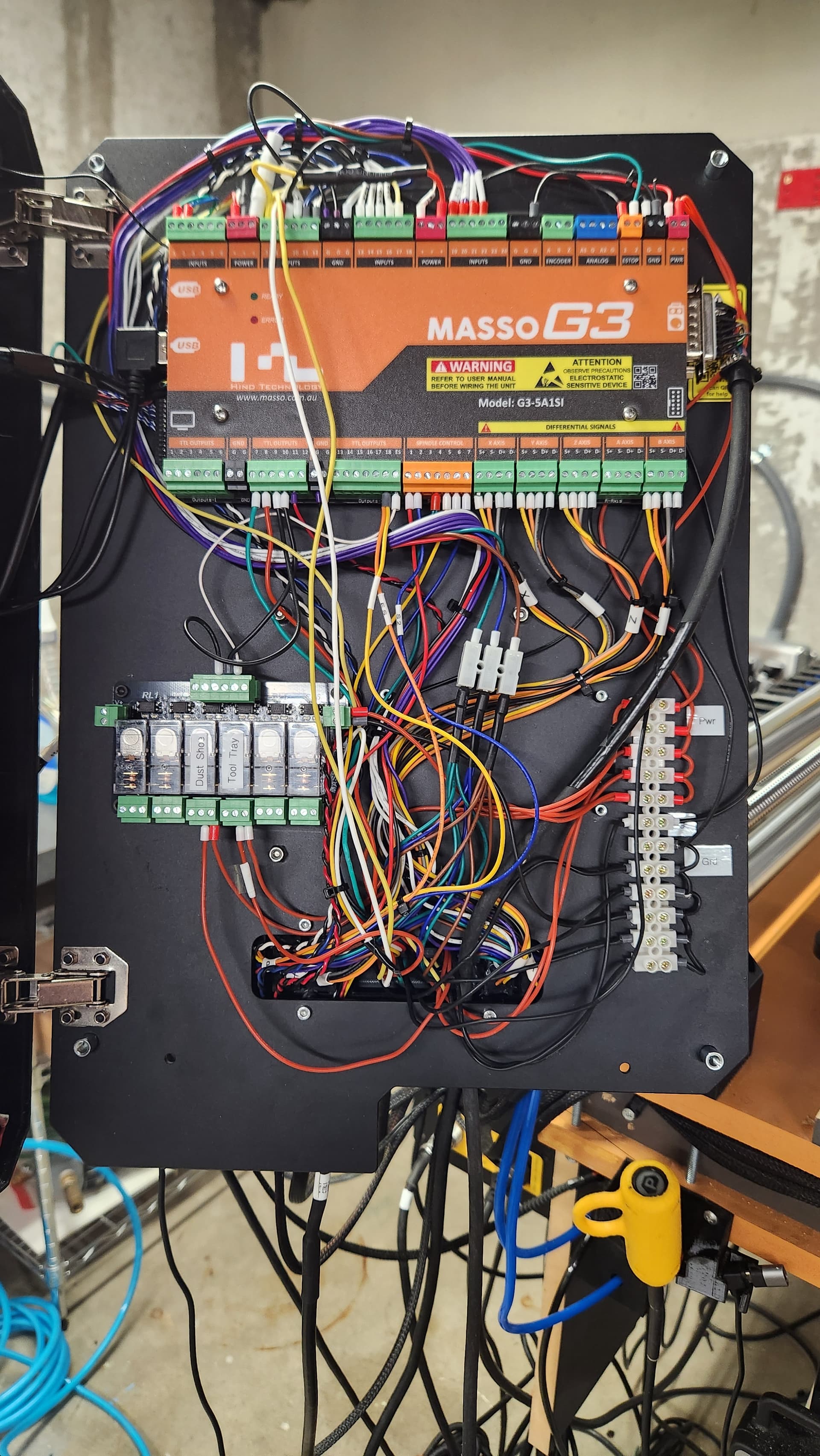
Inlets panel
4th connection down is strained, so I’m going to lengthen that lead, its the relay for the tool slide so no big deal
2 Likes
Yeah, that’s a pretty big strain. I would even consider moving it to the left side.
Looks great overall.
Didn’t think of labeling the relay inside,
What size wiring is recommended inside the Masso? I imagine the data and power/gnd are different sizes? What is a good source for the wiring?
Does anyone have an Excel file for labeling the Masso with inputs? If not I’m going to make one.
22 AWG is popular. Amazon?
I don’t know what your intent is. There are only a few inputs / outputs that are dedicated (output 11 & input 9, but input 9 can be used otherwise unlike output 11), everything else is what you plug in and program it for. Not to mention there are a lot more inputs/ outputs available than there are ports available to utilize.
I wanted to map out the wiring in case something happens to the system. Or if I’m adding something and it does not work I can go back to the old map. I will probably make my own cables because I want everything labeled and the cables dressed correctly.
1 Like
I’m not aware of one
I have one for Apple Numbers, something I use for home distribution panels (have done a few this year). Probably not an attractive format for most, so only attaching a screen snap with the row/column ids visible on the first one.
The gist of what I did is to use the “Merge Cells” function for overlapping zones of wiring. In the center column, the phases are laid out as odd-even, although I could have colorized them that way too.
MASSO is not laid out the same way, but thought the pattern might trigger improvements…

1 Like