Shapeoko 5 Pro Masso conversion and ATC and Machine Mods

I am posting this with Images over time. I will start with the ordering process and disassembly as for me the ordering process was not straight forward. I get the bug and just order without full research. The Pwncnc website is not the best with some information missing or not updated. Sorry Daniel.

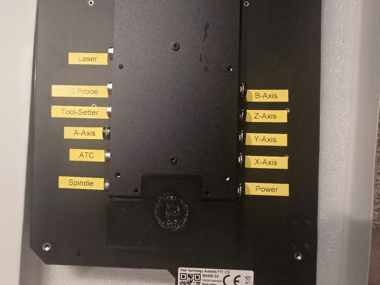
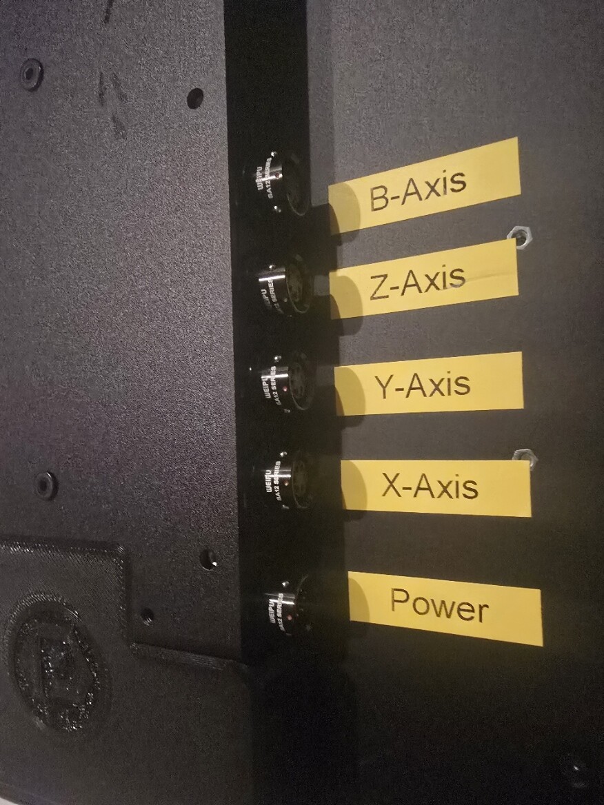
1. There are 2 Masso touch conversion kits you need the advanced to use an ATC. The Advanced Masso Touch comes with a Pwncnc rear plate with all of the connectors preinstalled and marked. Looks clean to me. I don’t see any image og the back of the basic kit. There is no VESA mount offered you ate on your own. Realize there will be a few cables coming into the Masso Touch so plan on a freeway of wiring that needs to be managed. The tool probe and touch probe is prewired in the advanced version, as is an extra 4th axis motor, (turning or maybe liftable dust hood for the ATC) I don’t have a need but it is there.

2.Touch plate and tool setter is extra and is not included with any kit.

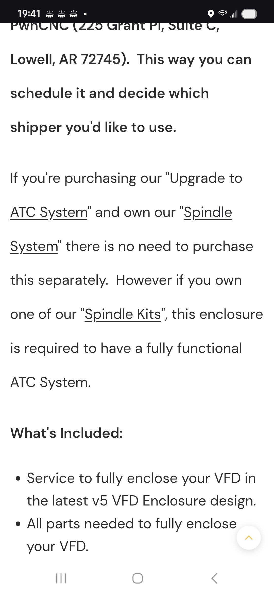
3. The VFD enclosure needs to be the V5 for the ATC and separate brake. My older spindle was not V5. You can send in your old VFD and have it converted, its not cheap. The difference is EMI shielding better plug. manual / auto switch that can be moved to the Masso Touch (additional cost for the mount), brake port, and sensor cable port to properly use the manual VFD tool change function. This also means the VFD has to be reprogramed or setup for this ATC sensor to work. Not sure I included everything here. This is specifically for the ATC. My older VFD would have worked with the Masso Conversion only. So yes I ordered a new VFD V5 because I can’t wait.

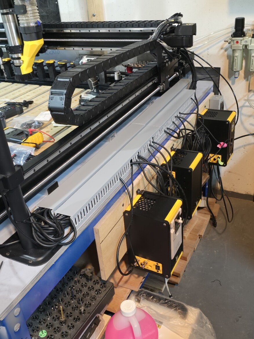
4. The newer Air controller has only one pressure regulator not shown on the web site.

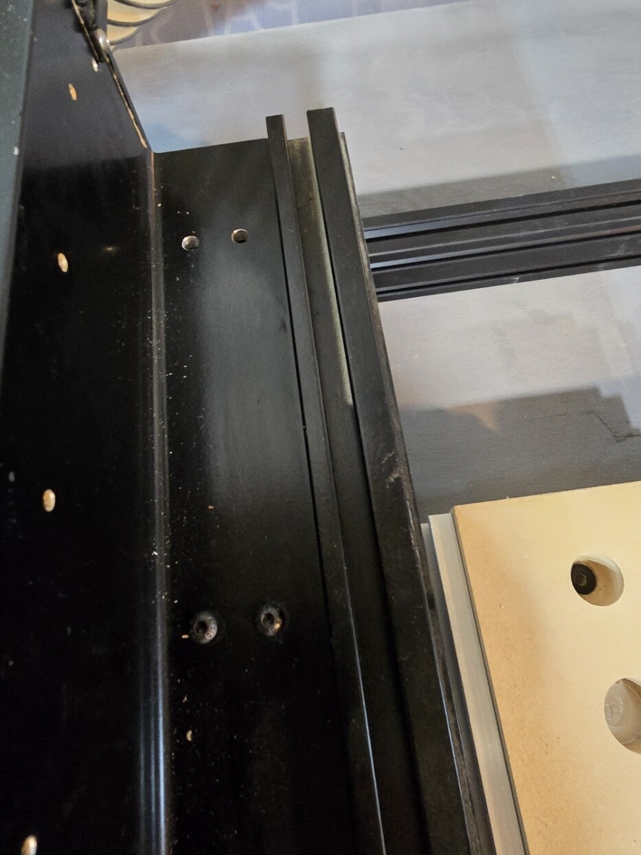
Disassembly, you should not need special instructions here. You put it together just take it apart

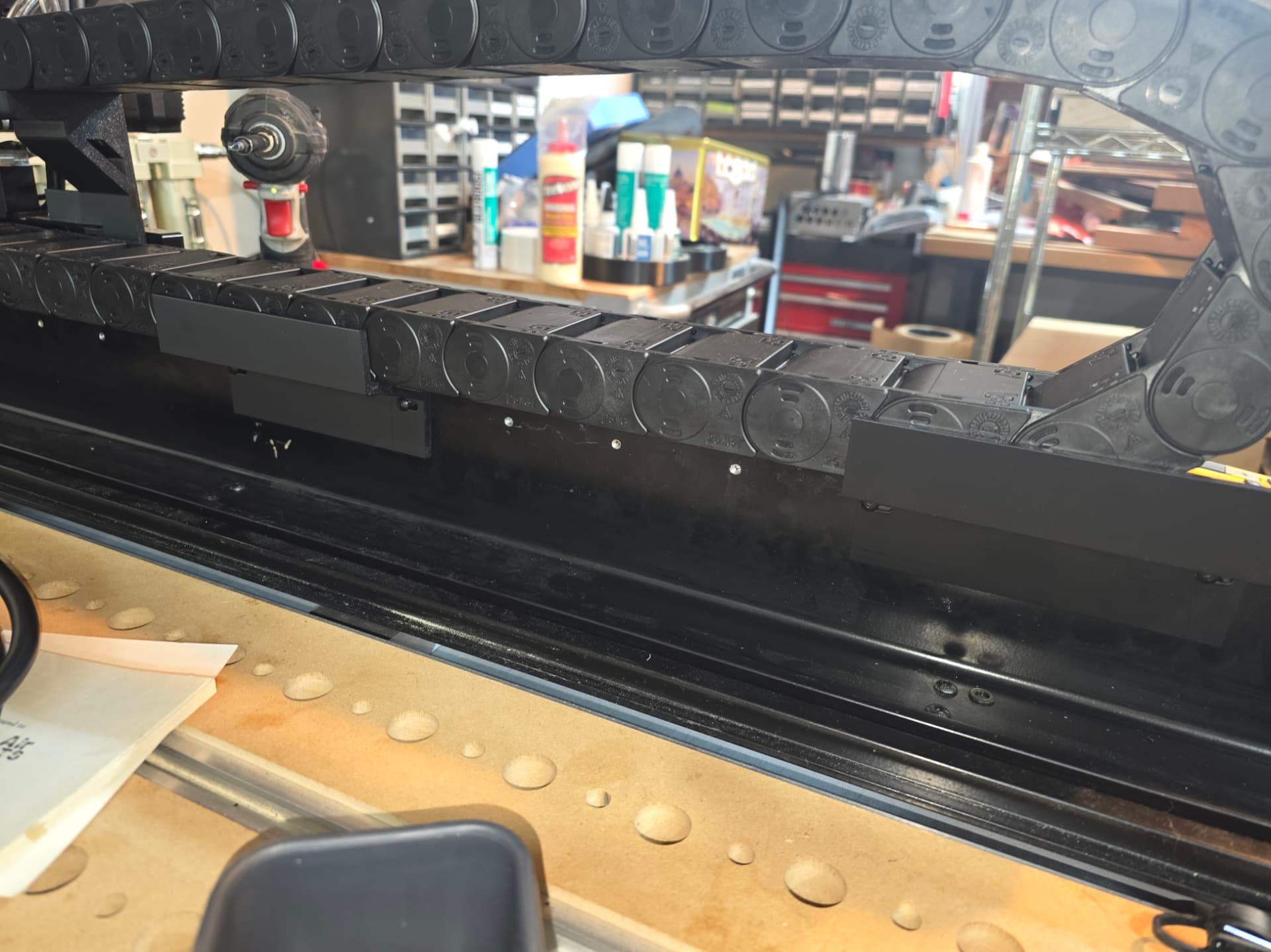
So first thing is strip the machine of motors cables and cable chains. Everything,

I removed all of the plastic covers on the Y axis frames. I removed the small PCB that lights up the carbide logo and has plus for the Shapeoko tool setter and touch probe. I also removed the Gantry light as it just peels off. Pawncnc has a replacement with cord for the masso (it is not wired in on the MassoTouch but comes with the connector).

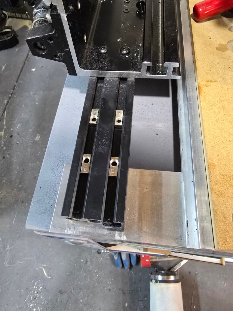
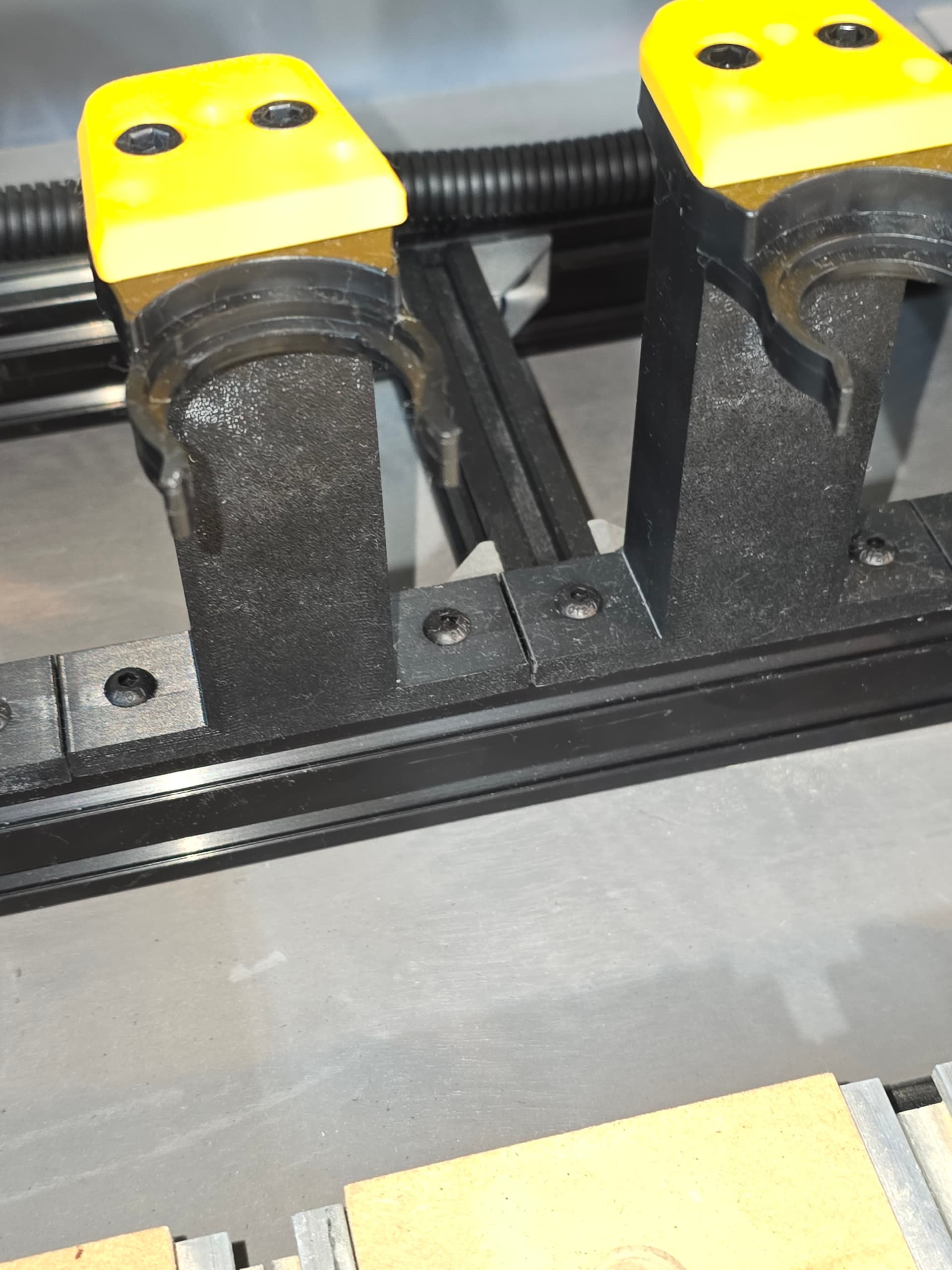
When you remove the motors you do not have to loosen the connector just remove the mounting screws an wiggle out the motor it will separate from the urethane cushion. You can then separate the connector off of the machine. Remember to loosen the diagonal screw first than the smaller set screw, otherwise the small set screw will be too tight to remove.

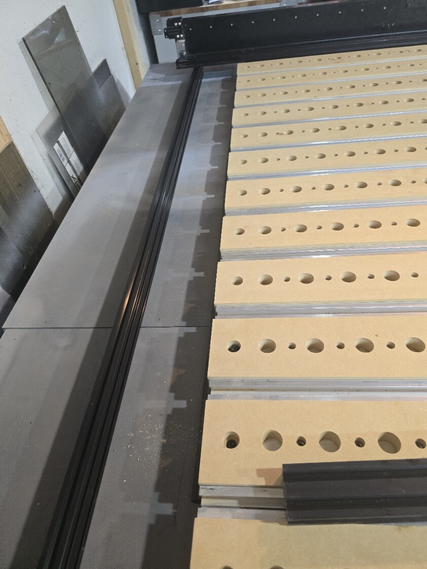
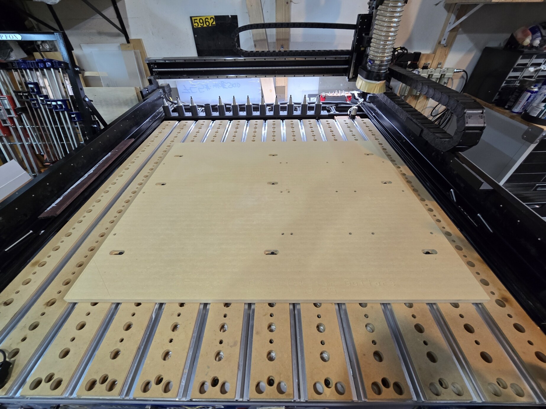
I so took the time to disassemble the machine to make several mods and to clean and lube the linear rail tracks and bearing blocks. The blocks do not drop bearings. Just do not remove the ball screw nuts. I use a lightweight grease as oil is hard to apply when the machine is assembled

Notes

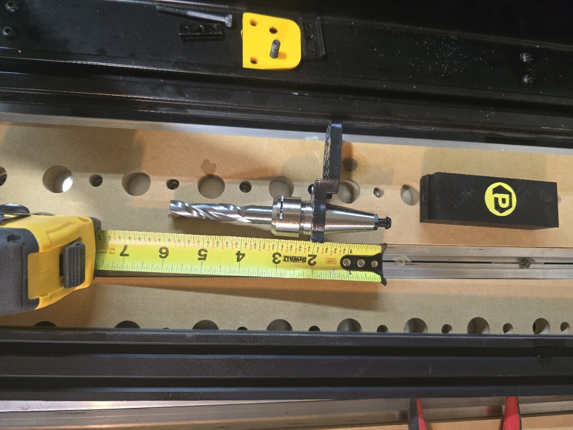
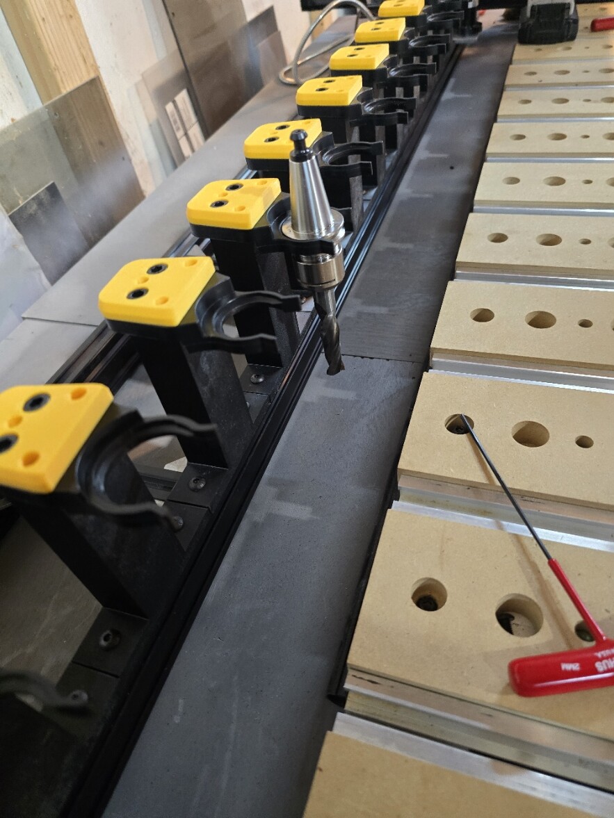
The machine Frame is not the Ideal candidate for an ATC, you will have to settle for some sort of offset of the bed in my case a 4x4. I am not doing sheet goods so the loss of work space VS not having to change tools by hand is a good compromise. Shapeoko’s Frane z heigh has only 6.1 inches of travel. So tool size is an issue and some sort of modification is necessary. Most people just remove one slat and a t track section. The onefinity would and is a better candidate But I do not own one. Using a vertical tool holder is not ideal and I went with the side mount holders.

1 Like

Number 1. The names (core/advanced) are from Masso. The core does not come with the connectors and is our most cost effective options. imo its worth it for convenience and features to get the advanced kit
Controller Portfolio - Specifications

Number 3. VFD upgrade is built into the ATC upgrade price from spindle system


Link to parameter changes: VFD Upgrade Parameters - PwnCNC

I am not knocking Pwncn most of my mistakes are mine. I dont expect Daniel to do everything and do it well. There is a Pwncnc difference between the core and advanced other than software, Ther is a minimal upgrage charge from the core to the advanced but you are on your own for the wiring on The masso touch maybe there will be a mail in upgrade?

1 Like

My plan to load tools

So how do you setup an ATC on a Shapeoko 5 Pro?

1.You can remove the left side wood strip and aluminum t track. Your tool can go below the table and between the cross supports.

2 Some have suggested drilling a hole and come in from the top. I have ruled out dont want large holes in the machine t track.

3. Move the gantry to the forward position and put your tools in the front of the machine. The issue I have with this method is it does block access to the bed and you will have to build a separate tool holder not attached to the machine.

4. you can place the tools on the rear of the machine like most high end routers. It is a mod using 2040 extrusions. This is the method I have chosen. Maybe invented Ha.

My plan

Remove everything from the machine everything. The y axis left and right are attached to the 4 cross members with two m6 screws on each. Drill a 5mm hold through the bottom side using the current holes as a guide. You should now have 4 5mm holes on the bottom side of each cross member. Purchase some long flat head m5 screws and countersink the holes so the screws are flush,

The spacing if these two holes is 20mm, exactly the same spacing as the y axis and 2040 extrusion. You should not distroy the existion screws if want to chang the machine back. I mounted one extrusion on each side usinf t nuts. You will have 4 cross pieces attached two extrusions.

So this lifts the Z-axis 20mm it does not look bad and gives access to flatting the spoil board in the X axis.

The next step is to attach the Y-axis on both sides to the extrusion again using m5 screws and t nuts. Leave this side loose for now as they will have more play than the origan m6 screws.

There is two reasons to do this it allows you to shift the gantry further back and provides an attachment point for the tool holders. Several longer 2040 extrusions.

This is enough for todays post. Hint the Y-axis has 5 sets of holes and only 4 cross pieces. You should have removed the two wire holding end caps already you don’t need these. Some have suggested drilling a hole and come in from the top.

I will in addition add risers to the gantry from Pwncnc they are 30mm tall. In total I will raise the gantry 50mm or almost two inches. Remember the spindle can be adjusted to offset any over zelous Z height issues.

1 Like

I didn’t take it as a knock, I was just adding further clarification.

I don’t think there will be a mail in upgrade option.

The key difference between the two with the wiring is the Inlets Panel, and a few preinstalled inlets.
If you wanted some accessories other than whats included, I believe its the Spindle inlet, Chiller inlet, A-axis inlet, probe inlet, tool setter inlet and ATC inlet, you would be responsible for getting those inlets.
I love the inlets panel, and I think it was done really well, especially as someone who likes to take their machine apart, or add something new, as without it things like my brake, diode laser, dry run laser and tower, i would have to either leave them attached or go inside and disconnect them. With the inlet panel, just disconnect all of them (i have a piece of tape and the name on the wire) and the other connectors, and I can move my masso whereever.

OK just a note here I am posting this as it comes together. I am 3d printing parts and then fixing them. So if the items I ordered from Pwncnc do not workf for me at least the parts will.

I will post a set of parts in stl format when they all fit. I am using ABS on a Bambu X1. In general If something is too small I just modify the design in fusion.

Here is the design or placement of the ATC tool holders. I will be adding further 2040 cross supports between both extrusions.

These are the screws holding thr Y-axis extrusion. This is the only mod requiring drilling into the original machine.

The machine was shifted 3.5 inches back from the rear of the spoilboard to the front of the first extrusion. I installed the Pwncnc gantry riser blocks, not pictured. The height of the gantry is looking right for the ATC.

Two extrusions to provide a stiffer Tool rack holder. I will be adding supports between the two. There is a slight gap to the table. I will see how it goes.

Yes all of these mods are for the ATC tool holders.

I have the ATC setup. Lots of screws. May not be the final Tool holder riser I will see how it goes.

The Support Structure.

Tool Holders Installed

With Tool. Riser is t shaped for extra suppirt 3 screws and accurate spacing for every tool. the Pwncnc V12 dust boot will not touch adjacent tools (not that it matters as 12 tools will be enough for me). There is additional space for 1 more tool. But 13 is unlucky.

Place for the Tool Setter. Yes I will paint the base black. To directly attach the tool setter to the Extrusion would require drill ing out the mounting holes. I used M4 screws and taped the aluminum palate.

Pwnvnc riser, Absolutly no rocking.

I did realise the Shapeoko front Y-axis plates will need to be cut in order to slide over the Y-axis Extrusion. OK 2 Mods.

I added screws and t nuts to add some supports under the rear ATC tool holder frame. as it was off the table. Acts like small feet.

1 Like

No I have not stopped, juat mired in wiring and 3d printing. Awaiting z axis chain.

I set the motors to 2000 steps which is something I read on Massos web site.

Installed the nasso Scratch cover and fount a second one in my kit. I guess I ordered 2..

Stuffing everything into 2 cable chains running off to the right side. Like a double stuffed oreo. I had to remove the carbide X-axis gantry cable chain mount on the z axis rear plate. I cut up two 2040 pieces and made a T. If it stays ill take a picture. the worst part of the wire install is the sticky spindle’s water tubes. if I have to readjust I will take out the Talc and powder every cable, Ha.

1 Like

I m again waiting for parts abd reprinting 3D items.

Decieded to purchase a taller Cable chain 50 x 25. The double stuff oreo on the Y axis is working but I would prefer slightly more space.

The shifted z axis needed covers

This is it but it needs some adj and fewer finger prints.

I installed the MPG Into the Masso Touch and realized that there is nothing to save the cable if it is accidently yanked. I added a loose Knot in the cable inside the masso touch close to the Pwncnc 3D printed cover. This gives some protection from stupidity. I will get a picture tomorrow.

I considered putting a cable retaining clip of some kind where it exits the masso, but largely deemed it unnecessary since I don’t have little ones who would go yanking on it or the like.

Onward and upward literally. Got the z -axis cable chain installed.

Here is the z-axis and the 4020 X -axis Cable Chain Support. I have caps to install on the extrusions pictured. The origiinal cable chain holder wass too flimbsy for everything. Two short pieces attached with bracks with 2 brackets to attach everything to the z axis plate

I am waiting for a larger cable chain to arrive for the Y-axis, 50mm x 25mm. Reprinting more 3D parts to fix the initial designs. I did paint the plate for the tool setter looks good. Also awaiting some cable management stuff and preparing to ground the machine. I should be done this weekend if I dont find things I still need to order or reprint.

1 Like

Wire Management Day. I installed the larger cable chain and started securing cables.

B-axis

Grounding Overkill.

How to hide long cables.

Still some more items to get done, hopfully first power on tomorrow.

The machine has been tested today after correcting a slight electrical issue.

I still have to install the chiller and compressor.

These are some of the 3d parts

The cable riser for the Y axis. Carbide used a molded plastic riser that I found was broken when I removed it. Originall it uses two screws but I added a third support using the Gantry forward poisition screws. I modified the design for a 25 x 50 chain. I will also supply the smaller 18 x 50 chain with a smaller rradius/

Cable carrier supports. You only need two as this cable is pretty stiff. I adapted the thickness to support M4 x 8mm screws as the holes are the backside of the Y rail which is very shallow. It will also fit the smaller chain.

The frront covers

The taller T shaped ATC tool holders (not the clip or Pwncnc caps)/

STL Files. Still working out some issues.

Y axis Cable chain support 50 x 25 https://drive.google.com/file/d/1F8qOVVQWsyD-udfXD6FbXWgxjy1_Dzfz/view?usp=drive_link

Y axis Cable chain support 50 x 18 https://drive.google.com/file/d/1__Z43DdvJbpt14yMXY6osycHwkaDmZt7/view?usp=drive_link

Cable chain support bracket https://drive.google.com/file/d/1cGDNljnkzlM1raOZdOr3z2y-U5-mqIlN/view?usp=drive_link

ATC Tall too riser T shaped https://drive.google.com/file/d/1zOrGVSrk_CNZMdAjaeonAk75fJ1oSvBC/view?usp=drive_link

Thats the stl files.

So its been awhile. I have had time to work out some issues in this setup and find new ones.

I dropped the ISO20 Forks and created a nore conventional drop in placement PWN type system. The forks were fine but seemed less likely to last as a 3d print. The drop in was less impactafull on the system meaning a softer tool change.

The second issue is the drag chain on the Y-axis. The placement to the inside of the machine is certianly an issue. The drag chain needs to be over the ball screw outside of the frame. The issue is mostly dust collection devices are up against the chain.

Some issues were motor distance per revolution The general guidlines are fine but not accurate enough. Had to use a dial indicator to adjust each axis as well as any Backlash. I found ATC tool zero’s were chaging after tool change tests on the F4 screen. Which ment relying on having accurate offsets so you dont have to zero a tool after each tool change. The indicator fixed the issue and the offsets were dead on after multiple tool zeros (offsets). Hopfully this makes sense.

I will post a picture of the ATC holder.

Some of the other issues were Carbide ones. The sensor mounts though convient for the retrofit are cheap plastic garbage. Any Impact will send the sensor bacwards and the bracket bending. Squaring the gantry invoves small forward or backwards sensor adjustments. You can do it with the homing offset which is the amount of travel from each sensor the axix makes after homing but its not recommended by masso. I used a granite square and fine test indicator.

All of these adjustments took time and patience. Every change from now on will require the ATC tool posistions to be reset. It can be frustrating at times.

Besides moving the drag chain over I am ready to start work. The chain move will require new printed parts And un hooking most of the cable on the controller side to move the chain around the gantry.

So this has been a bigger project than just hooking up some cables. You also need to figure out the masso software and reconfigure you Cam tooling numbers for each prior design to match the ATC.

If you have any questions just ask. I will post som images soon.

OK I think this is my last post on this subject.

After trying to use blacklash settings I disable it. OK set it to zero. as it was causing too much machine wobble when boring holes.

Turned auto zero back on as pre setting the ATC tool zero offset is problematic. Keep getting inconsistent offsets when testing and cannot trust it with expensive projects. Its not a Pwncnc issue, could be the machine or software. Not worth the hassle and i can live with the extra 20 seconts to measure tool lenght.

Have not tackled the Y axis cable chain placement over thr screw.

This is the machine as it stands.

If anyone has any questions please send me a message.