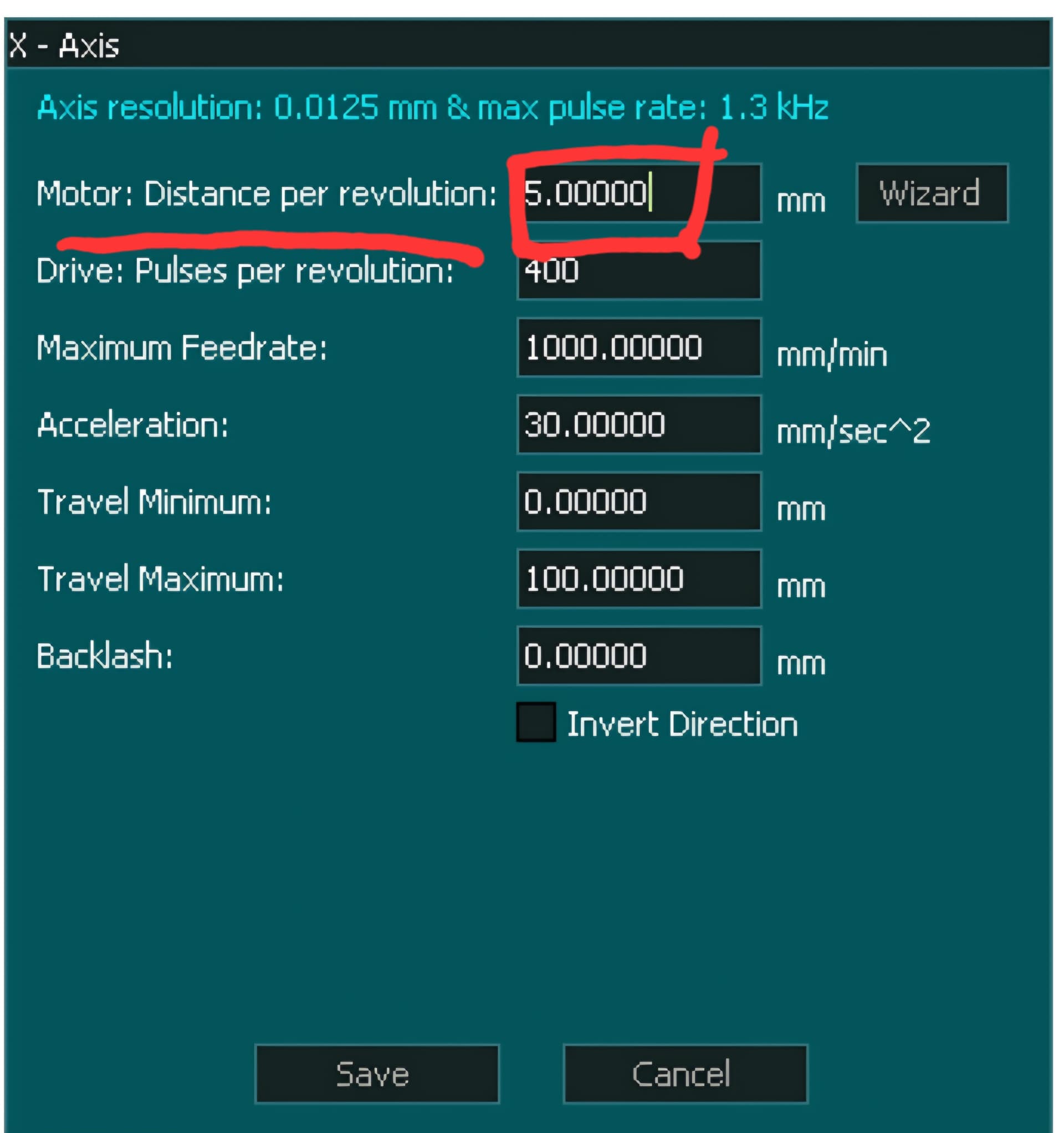
First, I want to declare that I too have my stepper motors set to 2,000 pulses per revolution.
After upgrading to the Masso first on my old Onefinity, and later on my new Dominator Pro, I tried a couple of different methods for accurately measuring distance traveled versus distance commanded, before going somewhat to the electronic geek extreme.
The first thing I tried was using what I thought was a reasonably good reference: a Woodpeckers 800 mm (~32") ruler. The problems I found with trying to measure like this were things such as:
- Parallax
- Divisions of even a millimeter were simply not fine enough
- Even with a V-bit, it was hard to determine exactly where the tip was on the ruler
- The measurement process itself was just not repeatable or precise enough over any appreciable distance
After a whole weekend afternoon of frustration, coming up with wildly different numbers in all directions after every single attempt, at least I can say I now have my first finely crafted Woodpeckers product!
The second thing I tried was a 36" long, flat, linear rail DRO from iGaging (Easy-View DRO, model 35-736-P+), designed for sticking onto things like a Bridgeport mill. It claims a resolution of 0.0005" and an accuracy of ±0.013". I screwed the rail down to the spoilboard, attached a #8-32 machine screw and nut to the shuttle, and chucked this machine screw into the spindle collet. But this too suffered from a few shortcomings and challenges, including:
- Getting the linear rail to stay flat enough without sagging in the middle, which caused binding
- Getting the rail to be perfectly perpendicular to the spindle axis without binding
- The quality of the sensor not being precise enough over multiple measurements or appreciable distances
Basically, think of this as a cheap 36" long Chinese-made digital caliper versus a high-precision Mitutoyo. This came close to what I wanted, but again, it was somewhat frustrating after a day or two of trying.
At this point, I put all of this information, about what I did and what I wanted, into ChatGPT, asking it what it thought were some good options.
One of the things it suggested was a class of laser measuring devices used in industrial manufacturing, primarily in automated assembly lines, to detect when a product passes or reaches a certain point. These devices are extremely precise and reliable. The manufacturer that stood out as the best option to me was the Japanese company Keyence. They offer a wide variety of models, ranging from ones that only work at extremely close distances (less than 25 mm / 1") to the model I chose, which has a minimum distance of 200 mm and a maximum range of 600 mm.
These lasers are made in two separate parts: the laser “Amplifier” unit, which connects to a DC power supply and has the digital LED readout, and the “Sensor Head,” which is what actually emits the laser.
Brand new, these Keyence lasers cost hundreds of dollars each, but then there’s eBay, where there are plenty of used ones pulled from production environments and still in great shape. I ended up with an IL-1000 Amplifier for $45, and an IL-600 Sensor Head for $70. Since I didn’t want to solder anything, I also bought a new factory-branded cable that runs between the two devices for $50 (Keyence OP-87056).
Then I:
- Designed a 3D-printed holder to attach to the front spindle mount of each machine
- Placed a white piece of foam board on the machine bed to have something for the laser to bounce off of for the X and Y axes
- Loaded up an Excel spreadsheet on a laptop with multiple columns for incremental distances from 20 mm to 500 mm, doubling the distance each column
Sitting back in a chair, I proceeded to issue commands such as G90 G1 X20 F800 to move the spindle to 20 mm, let the laser settle for 30 seconds or so, and enter what the readout showed into the measured value for that spreadsheet column. Then I moved to 40, 60, 80, 100, etc., and kept entering the values from the readout into Excel.
As I entered the values, I had a final column on the right that automatically averaged each of the measured distances and their respective scaling factors, combining them all into a single new “distance per revolution” value to enter into the Masso.
With the new value in Masso, I moved the spindle back to the start, reset both the CNC and the Keyence laser head to zero, and ran the entire test again. I did this a total of three times per axis, and as the following screenshot shows, I managed to get the machine calibrated to what I would call more than good enough for government work.
Disclaimer: the text for this post was reviewed and modified by AI, resulting in the melting of approximately 2.77 square feet of the Arctic ice shelf.