I am having some issues wiring my new spindle from PWNCNC with my existing system. The pin orientation isn’t the same on the spindle I received and the one in the PWNCNC knowledge base. I will attach both images here.
Does anyone know the pin orientation of the spindle I received (photo attached) or can point me in the right direction on what the pins correspond to? It will only let me attach one image, so here is a like to the PWNCNC drawing I’m referring to 110v 1.5kw er20 water cooled spindle
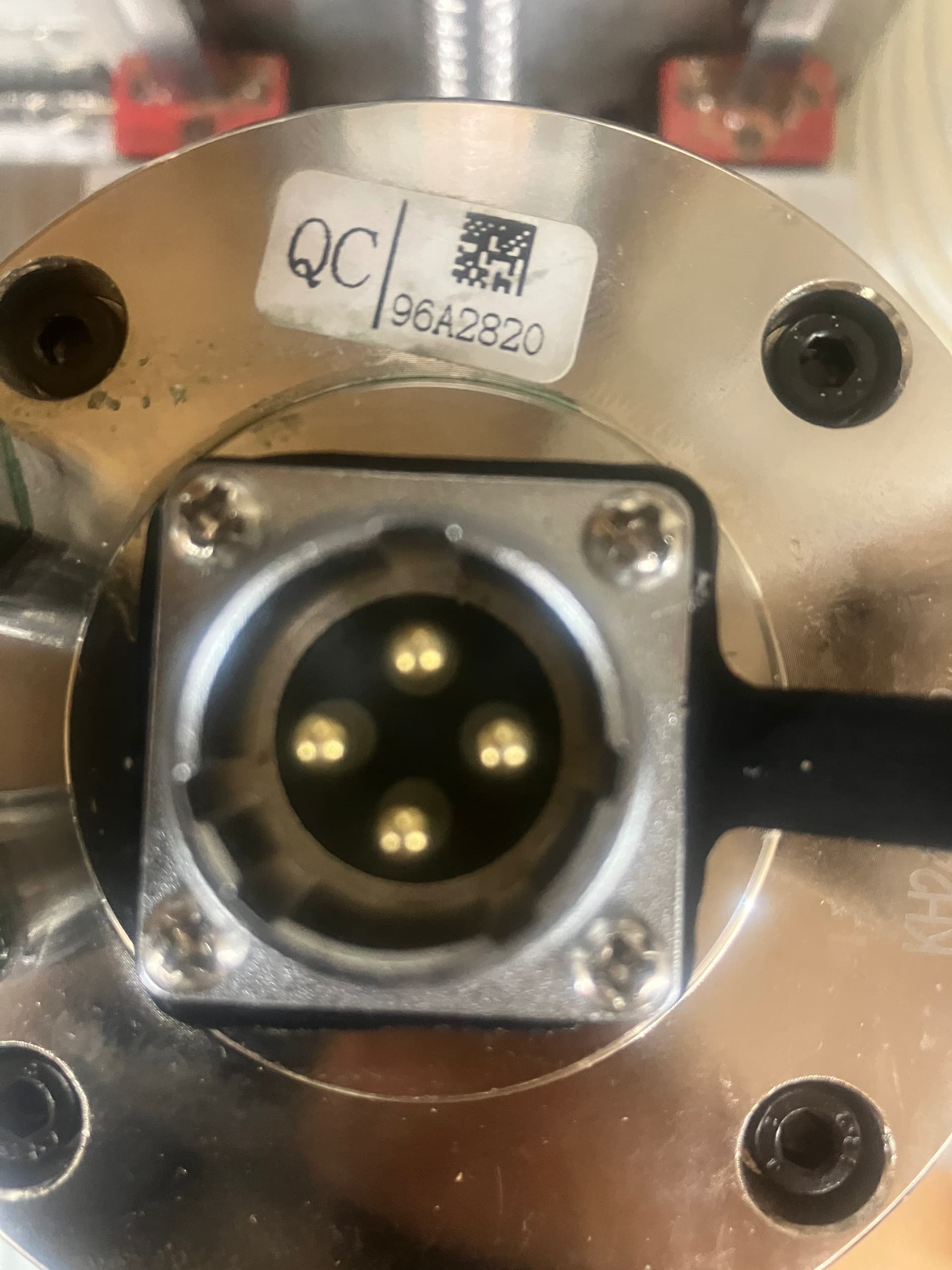
You can see from the attached images that the pins on my spindle are rotated 45 degrees from the layout on the attached drawing from PWNCNC. But I don’t know which way they rotated. Is the pin facing the top of the image U or V?
Is this motor for one of our vfd’s? If so are you using one of our spindle cables? If so then the orientation doesn’t matter.
These are 3-phase motors which means 3 pins are power (orientation does NOT matter) and 1pin is ground. Your primary goal should be to identify which pin is ground. This is pin 4… however it may be hard to tell so you can remove the 4 screws holding the spindle top on (not the connector screws but those black screws).
The ground pin will be the one that has a short wire coming from that pin and attaching to the body of the spindle underneath that cover.
Once you know which pin is ground… then wire the other 3 wires up to U V & W. Start your spindle turning and if it is turning the wrong direction, then swap any two of the 3 wires and it should start spinning in the correct direction.