I’m a confused newbie here. I ordered the Spindle System × 1 2.2kw 220v ER20 80mm 2-pole 400Hz Water-Cooled for my AltMill. I’m in the assembly phase where I need to connect the wires and make an extension cord for the VFD.
My assumption is, once everything is wired when I start the AltMill and transfer the gcode the spindle will respond and the water will start to flow.
I’ve connected all of the wires for the AltMill but have not applied power. I want to confirm I’ve done everything correct visually before I apply power. Here is where I’ve run into problems.
(1) Where are the instructions for connecting the spindle to the AltMill Super Long Board
(2) I have one cable that my son connected to the Super Long Board, I’m not sure where he got instructions to make this connection. We don’t know where the other end of the cable goes.
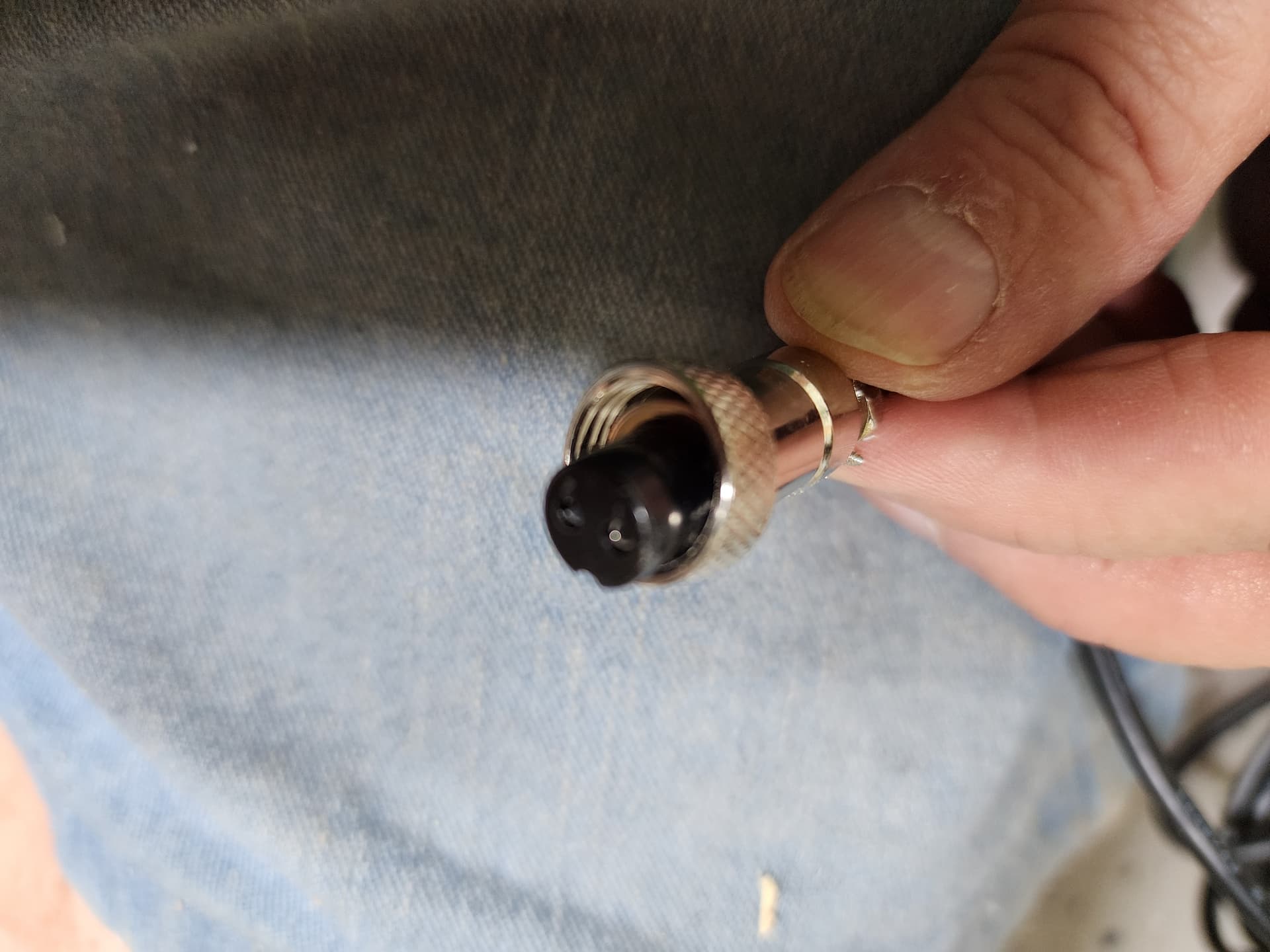
Following is an image connected to the Super Long Board
Here is the other end, that we don’t know where to connect.
PWNcnc don’t know where to connect this I’ll add the image to the thread. DAMN restriction, does not allow new users to add more than one image. Sorry to throw rocks but this is the pits!
(3) Where are the instructions for connecting the Spindle to the AltMill. Please give me the URL
(4) I also ordered the pump and need the instructions for installing it. URL please
(5) How do I get the pump to run when the spindle is running automatically?
As a newbie, I did expect to encounter issues. Everything is taking MUCH, MUCH, MUCH, longer than I had estimated, partly because this is a HUGE learning curve for me. I’m an old fart and get confused easily… LOL!!!
PwnCNC also has a YouTube video on the Super Long Board that is 4 months old: Ultimate Guide: Sienci Labs SuperLongBoard Modbus Control.
(2) I have one cable that my son connected to the Super Long Board, I’m not sure where he got instructions to make this connection. We don’t know where the other end of the cable goes.
Maybe the link for (1) will answer this question. I imagine the other end of the cable needs to go to the PwnCNC VFD enclosure’s Modbus port. Your Super Long Board will send commands to the VFD which the VFD will then convert into power for the spindle. What connections do you have on the side of your VFD? I believe PwnCNC tries to make each connector unique so that it is difficult to get the connections wrong.
(5) How do I get the pump to run when the spindle is running automatically?
Does your VFD have an “IOT” port on the side? It can be used to turn on the pump. PwnCNC sells an, IoT Power Strip, that can be used with the IOT port on the VFD.
Eriz, we have success with the power. I had seen the instructions (#1) you mentioned but kept telling myself it was not for my SLB (Super Long Board). Twice again I read through it and realized I could easily remove the cable from the two-position plug and insert it into the left two of the four-position plug that was in the SLB. Success!!!
In an attempt to answer your question regarding “IOT” I found the connector on the VFD for the power.
As you can see in the following image I do have the IOT connection which is to the right of the power cable, the other end is attached to the SLB.
The VFD has connections on two sides. It would have been much better (IMHO) if all of the connections were on one side. The VFD did not come with a mounting bracket so my son made one and allowed about 6" of open space between the AltMill leg and the VFD. this allows me to access the connections on the left side of the VFD. On the left side I have the connection for the power and the IOT. Now I need to get an IOT. Following is an image of the RIGHT side of the VFD
DAMN I’m still restricted and cannot include more than one image.
Following is the SLB with the VFD power connection in the correct location.
Much thanks for your help. Hopefully just a few more days and I will have a working CNC!!!
AH!!! Yes the VFD came with a mounting bracket, but I did not know what the heck it was for, I did not receive any instructions to help me. Instructions would have been super helpful. Until I saw your image I did not know what the plastic piece (bracket) was for. OH well, now I do have a super nice alum bracket. LOL